After completion of my backyard observatory project based on the ExploraDome, I began to build the automation system to allow the dome to rotate and follow the movements of the telescope mount.
Based on cost, I chose to use the semi-do-it-yourself controller called LesveDome provided by Pierre de Ponthiere. With this system, you purchase a software license for the ASCOM compliant dome control software from Pierre and you build the actual hardware from a combination of off-the-shelf relay boards and a USB IO controller board. I highly recommend this system.
Track and Motor - The motor and track assembly in the observatory are provided by
ExploraDome as an added purchase. The first step was to install that hardware.
I removed the support bracket used to hold together the seams of the wheel track. This bracket is replaced with alternate version that does not have the extra lip. I had 4 of these left over, not sure if they were pre-planned for this. Finally, I attach the drive track which now braces the seam.
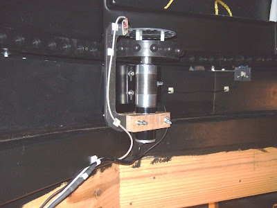
Once the drive track is in, the 12V DC motor and "acorn drive wheel" are installed. This is part of the kit from ExploraDome. The fastening plate is a spring loaded barn-door hinge that keeps the drive gear in contact with the track. As the dome rumbles around, the whole assembly moved around quite a bit. Note that due to the extent of the motor housing, I was only able to choose the octagonal corners as locations for the motor. Here I have it placed just West of due North.
Due to slight deviation from roundness, the gear will sometimes skip a hole when turning dome CCW. In that direction, the gear is able to "climb" out of its holes. This happened at a spot where the track was rececess back the most. I shimmed the track out with some duct tape and increased the spring tension on the motor retaining bolt. Limiting the rotation speed also helped.

Once the motor is installed, the dome can be rotated by applying either positive or negative 12V across the motor leads. Initially, I just used a momentary SPCO switch, i.e., (on) - off - (on), to manually control the dome until the automation system was completed. I also integrated that switch into the automation circuit to provide manual override or to rotate the dome without starting the computer.
Rotation Encoder - Based on the instructions from Lesvedome, I fitted the azimuth rotation motor with a rotation encoder. I fabricated a plastic commutator wheel with 3/8" holes every 15 deg and mounted on top of the acorn gear. A pair of IR/LED sensors generate a Gray Code to determine rate and direction of rotation. It is critical that the sensor, wheel, and motor/gear all be part of one non-flexible assembly. The motor and gear bump around quite a bit as the dome turns; fixing the sensor bracket to the building itself would not work. I built my version by clamping around the bottom of the motor with a pair of hardwood blocks. This holds the "C" bracket in place to position the sensors to read the holes in the wheel.
The rotation encoder is constructed from a pair of EE-SX1042 optical encoders glued together and onto a plastic jig. The small circuit board contains a resistor and diode and connections to the control board as described on the LesveDome website. I can losen the jig and reposition the sensors slightly. This view also shows how I mounted the commutator wheel on three spacers screwed into the plastic part of the gear thus avoiding having to figure out how to redo the main motor shaft.

Home-Position Sensor - The home sensor started out as a magnetic reed sensor. The hard part was figuring out where to mount it. I loosened the gear track at a joint in order to be able to screw the movable part of the sensor underneath the track. I then fashioned another plastic jig to hold the stationary part as shown. When I tried to simply attach the stationary part with screws vertical into the rotation-ring base, I could not get the switch to close. By rotating as shown, it worked. Obviously the ideal would be to mount it vertically directly under the movable part but there is not enough clearance.

It was not long before the magnetic reed sensors were giving me problems. I found that there was too much hysteresis in the swiching points. I changed to a new mechanical sensor. From a piece of spare oak, I fabricated a curved section that is screwed to the bottom of the the drive track. Again, I did this near a track joint so I could loosen just a bit of the track. A roller/lever switch is mounted and adjusted so that it just closes at the apex of the curved section. The broad curve is critical when the dome rotates CW to prevent catching and jamming the end of the switch. My first attempt self-destructed several time until I figured this out.
The body of the roller/lever switch can pivot for adjustment by loosening the nearest screw on top. This pivot point allowed my to adjust the dead-band range of the switch. Once everything was fixed, additional tweaks were possible by bending the lever very slightly.
Controller Hardware - The next step was to build the LesveDome control system. At its heart is a Velleman 8055 USB IO Control board which I built from a kit. The LesveDome driver software is written to work with this generic experimenter's board. The board is connected to several different relay boards to drive the rotation motor and optionally the dome-shutter control motors. I only constructed the dome-rotation since I did not really have a need for remote control of the dome shutter doors.
A suggested circuit by Charles Harrow is published by the Lesvedome project and various modifications are given by other users. I based my circuit on "ELK" relay boards as others have done but made a few modifications to address some of the problems I was having. Here is my variation on the standard circuit:
My main modifications were the inclusion of a motor-speed control board and to alter which triggering mode to use on the ELK boards since some forum users were having problems with the ELK924 triggering all of the time. Here is a post I put on the LesveDome Yahoo group regarding the triggering problem
The root problem is that the ELK board in "sensitive mode", triggers on a very small current injection into (T-), small enough that the pull-up circuitry in the input section of the 8055 can source this current. Note that the relay boards are powered at 12V and the input of 8055 is only pulled up to 5V. I reasoned that from the ELK ckt point of view, the 5V pull-up actually look "low" enough to to act like the input to the relay board has been pulled down and negatively triggered. ... There are 2 alternative solutions:
(1) Force the relay board to act as a voltage switched device - This was my approach. Ensure that the 8055-Output2 has to pull the boards negative power rail down to GND along with the trigger input. Minor current flowing into 8055-input logic will do nothing because the circuitry in the ELK board is not "grounded".
(2) Shut down the inappropriate current path - This was Joe's approach. The diode between Out2 and In4 only allows current to flow FROM In4 TO Out2. Thus, if Out2 is pulled to 0V, current can flow from In4 to Out2 and be detected by the 8055 as an input signal. However, If Out2 is not enable, the diode prevents current from exiting the 12V circuit of ELK input, into In4, through the pullup resistor, to the 5V level.
In my circuit diagram, I chose to trigger ELK924 in
"insensitive" mode. The reverse-current protection diode D0 prevents the Dig In 4 circuit from triggering ELK924 all the time. If Out2 is pulled to 0V, current can flow from In4 to Out2 and be detected by the 8055 as an input signal. However, If Out2 is not enable, the diode prevents current from exiting the 12V circuit of ELK input, into In4, through the pull-up resistor, to the 5V level.
I also included a motor speed control board MX033. This allows the rotation speed to be lowered. This was critical since I have problems with the drive wheel on the motor "popping out" of the drive track, especially when rotating the dome counter-clockwise.
I posted another comment to the Lesvedome Yahoo group regarding the function of diode D14:
The windings in the DC motor ( or the windings of any inductor such as the energized coil of a relay ) resist changes to current flowing through the winding. When the supply voltage to the motor is disconnected, current previously flowing through the motor cannot stop instantaneously. The purpose of the diode is to given the current somewhere to flow after the switch disconnects the motor from the power source. Without the diode, a large voltage spike is created across the windings and can cause various problems in the rest of the circuit. The diode needs a current rating at least as large as the largest current that you expect to flow through the motor... that current is much larger if the motor is stalling.
Further complication ... in the circuit in question, you can't simply place the diode across the motor windings because the current in the motor could be flowing in either direction ... which way would you orient the diode? Instead it has to be placed between the on-off switch and the direction-changing switches at a location where the voltage is always of the same polarity. Technically, D14 bleeds off the motor current when K1A-A is switched off. On the other hand, it does address brief condition where K2A-A and K2-B are switching and neither is closed for a moment.
Another note, this motor-current-keeps-flowing problem is why, when the lesvedome driver software changes dome direction, it pauses in the off state for a moment. This allows the original current to bleed off through D14 down to zero before trying to switch in to a configuration where the current starts flowing in the other direction. Without this pause, you can damage the power-supply or trip voltage protection circuitry.
Here is a picture of the ELK relay boards, the USB control board, and the motor speed control board mounted on acrylic sheet.
Next is a view of the control board with all of the connections in place. External connection wire cables go to: 12V Power Supply, USB to Computer, Home Sensor, DC Motor, Rotation Encoder, and Manual Rotation Switch. Relay boards on the right are for future use for shutter control if I ever include that. In the middle is the motor-speed control used to reduce the rotation speed of the stock ExploraDome motor.
I then mounted this board in an in-the-wall electronics housing and included a power-supply. A front panel covers the assembly.
Controller Software Configuration - Once the hardware was completed I needed to configure the driver software. Here are the key settings for the dome size and encoder wheel that I am using
Here are the mount geometry settings for my CGE mounted on the central dome pier with a TMB-130SS refractor and guide scope:
And finally, the ASCOM Celestron driver parameters for the mount:
With all this completed, I use POTH to perform the dome slaving calculations. I first tried to do the slaving in MaximDL but had better results using POTH.
The project is finally completed and working as desired. The LesveDome solution seems to work very well. My on-going frustration is still the "roundness" of the ExploraDome track system. I have never been able to get the dome to rotate smoothly all the way around.
Update September 2012 - I understand that ExploraDome now supplies a rigid aluminium track assembly to address the roundness problem.
Here is the dome in action tracking the mount during an imaging session ... now if I could just automate away the local light pollution ...


