Showing posts with label Jayco. Show all posts

Tuesday, December 15, 2015

Yet Another Trailer Antenna

Yes, another year, another trailer antenna project for our Jayco Jay Flight 28BHS ...


My first project was a WiFi access point mounted on an antenna mast. This worked well as a system but failed to be practical due to a lack of usable WiFi service in the parks we visit. My next attempt was to simply mount a passive Verizon LTE antenna on the mast and attach that to a MiFi mobile hotspot. This also worked but, since our cell service is AT&T, we were provisioning the Mifi on a pay-as-you-go basis, an expensive and frustrating process. Recently, we found that AT&T has started allowing iPhone tethering on its normal data plans so it would be much simpler to boost the iPhones and let them both access the network directly and use them as hotspots for the laptops.

I looked into setting up an AT&T voice and data cell booster. Reviewing available technology was encouraging as I found that multi-carrier voice and data systems are now available. I chose the weBoost Drive 4G-X amplifier from Wilson Electronics and combined this with a marine-grade multiband antenna and an internal ceiling patch antenna from the same manufacturer. The patch antenna is similar to the one we use in the house to boost voice signals. I opted for the marine grade antenna since we often camp on the coast. I ordered the parts from Wilson Amplifiers, a distributor here in Texas. I can recommend both of these companies, despite the confusion in names!

When I received the parts, the trailer was unfortunately in the shop getting repairs done. My tests were, therefore, initially attempted in the house and in the truck. I was plagued with feedback problems between the two antennas and had resigned myself to possibly using the mini personal patch antenna that comes with the booster, a unit intended to provide a signal only within a 2 foot radius. A call to technical support at Wilson Amplifiers which they escalated to Wilson Electronics after answering the basic questions proved helpful. They both patiently listened to my issues and gave me good information on how the booster works and what to expect. Fortunately, when we got the trailer back and I did some real tests, the feedback problems did not reoccur, perhaps due to reflective foil insulation in the roof which I had forgotten was part of our installation package.

The permanent installation started with the tedious task of figuring out where I could route cabling. I wanted the inside antenna centrally located on the ceiling near the kitchen table and I wanted to reuse the "electronics shelf" over the table for the booster unit.

I started by drilling a hole just large enough to pass a male N-connector of the patch antenna and placed so that one end of the antenna would line up with a ceiling joist. As I found out, my chosen location was clear of other ceiling fixtures for a good reason ... this is where the air conditioning duct passes in the "attic" space to feed the rear vents. There is about a 1" gap between the duct work and the ceiling panel. Enough room to pass a cable but hard to drill through without scoring the duct. Hey, at least I didn't end up drilling a hole into the duct.


I next removed the speaker from the ceiling (show circled below) to give myself a place to reach into the ceiling space to fish cable. The decorative trim and grille cover slides tightly over the metal speaker housing. I am not sure if there is a tool to remove it with but I managed to wedge it off with a flat head screwdriver. There are two joists between the speaker location and the hole I made for the antenna. These are not solid but are trusses and have space to route a cable through.


In the electronics shelf over the table, I drilled a smaller hole in the ceiling just large enough to pass a male SMA connector. This hole is just to the right of a joist and in the same joist space as the speaker. This made it easy to use fishing tape to pull some cord back to the speaker hole. However, pulling cord from the patch antenna hole to the speaker hole proved more difficult with the joists, AC duct, and miscellaneous wiring to navigate past.


In the electronics shelf, I drilled a second hole directly below the first (yellow cord) that leads down into the space behind the entertainment unit and which is already full of cabling. This photo below is of the wall separating the back bedroom from the entertainment shelf. From here, I drilled a hole back into the the entertainment cabinet below the DC power plug I had installed in a previous project.


Here is where the hole comes out inside the cabinet. The yellow cord continues up and to the left to the electronics shelf as described in the earlier picture.


With the holes completed, I routed a section of RG-58 coax with a male N-connector and male SMA connector along the shelf that I modified in a previous project situated in the rear sleeping area. This cable follows the yellow cord. All of the slack in the coax was tucked out of sight into the entertainment cabinet.

Along the shelf, I used stick-on cable trays to keep the coax from catching on things. This coax attaches to an N-connector bulk-head that I had installed as part of last year's Mifi project. The little frame outlines the section of wallboard that I had to remove to access the external siding of the trailer and to mount the bulkhead. Now, it is a removable panel. Ideally, I would have tried to route this section through the ceiling as well.


Here is where the bulk-head connector come out, behind the ladder and about 20" down from the roof-line. If I were doing the project from scratch, I would probably move the entry point further up and more central to reduce the cable slack. However, I already had the connection point installed.

I added a right-angle N-connector to protect the coax from getting bumped and connected another section of RG-58 enclosed in a protective split loom. This section has a male N-connector on one end (shown) and a female SMA connector on the other. By the way, the cables did not come with connector combinations as I am using. The antenna kits comes with a 20' extension cable with SMA-female and SMA-male connectors.  I cut this in two parts and crimped on male N-connectors on the two ends. I used the part with the SMA-female to route the the external antenna and used the other half to route from the booster to the patch antenna. I ordered an additional cable with N-male and SMA-male from Wilson and used it for the run along the shelf.  By the way, not all N-connector RG-58 crimp connectors are created equal. The ones sold by Wilson Amplifiers were of good quality and had a solderable center pin.


My adoption of marine parts continued on the roof. Shown here is a Shakespeare ratchet antenna mount, part 4187-HD, attached to a Shakespeare Galaxy 48" fiberglass mast section, part 5228-4. I found both of these locally at West Marine. I screwed the mount onto the roof using stainless screws and covered with the same Alpha Systems 1015 self-leveling sealant that I used on the solar panel project. The nylon mount that came with the antenna was not sturdy enough to use with an extension mast.


The ratchet mount is great. It allows the antenna to be folded down parallel with the roof and raised in seconds. Unfortunately, the antenna radials are very fragile (I already broke one) and are likely to puncture the roof covering if things rattle around while driving. To the rescue ... foam.  I sacrificed the end off of a therapeutic foam roller lying around the house.


I also screwed a stainless "top saddle" from the marine store to the roof and used it to strap the antenna and foam block down solidly. Notice from the inset picture that the radials are safely above the roof.


When in camp, I can simply unstrap the tie-down, release the ratchet, lift the antenna, and re-tighten ratchet. I can even slide the foam block down if desired. I still have to get on the roof but I don't have to carry any junk up there with me now.


Back inside the trailer, I mounted the patch antenna on the ceiling with the hole placed at the far end. The closer pair of screws go into a ceiling joist, the other pair only catch the ceiling plywood.


The booster amplifier gets screwed to the back wall of the electronics shelf. The upper coax goes to the patch antenna via the attic space while the lower coax goes to the external antenna via the entertainment cabinet an the bunk shelf. The third line is the DC power which either plugs into the AC outlet just to the right or into the DC cigarette light plug intended for the TV.


Wow, rarely do projects like this come out with all of the wires pointing in the right direction. The important test here is that all of the lights show green! This indicates that the booster is not reducing its gain to compensate for feedback between the antennas. In the end, there is about 4ft vertical and 10ft horizontal separation between the two antennas. This is about what I was testing earlier so I assume that the foil insulation is enough to block the potential feedback path.

The completed antenna extends well above the roof line, clearing all of the other junk up there. Running a test in the yard, the 4G data signal boosted from 1 bar to 4 bars.  Time for a real field test!


Dec 27 - Trip to Mustang Island State Park last week. The booster made the different between a reasonable LTE signal inside the trailer vs. nothing ... yay!

July 5 - After six months and several spring trips to the coast, the repeater has been well worth the effort and expense.

Sunday, February 10, 2013

Conversion of 30A Trailer Supply

This weekend's modification project on the Jayco Jay Flight 28BHS trailer was to replace the shore power cable with a detachable system based on parts from Marinco as others have done.

Here is the problem. This trailer, unlike our last one, uses this so-called "mouse hole" for the 30A electrical cable used to connected to shore power.  This cable is permanently attached internally and you pull the whole length of the cable out through this hole.  Jayco warns that the cable should not be used partially extended.  Probably because heat is not adequately dissipated.

I really hate this cable system.  When the cable gets muddy, you either have to clean it carefully prior to stowing it or end up pushing mud into the trailer. Worse, when the weather is very cold, the cable gets stiff and is impossible to shove in the hole. I also find it tedious when I need to quickly connect shore power to the trailer at home.

To begin, I removed the three screws from the mouse-hole assembly and pried on it a bit ... it came right out.  There was no lap sealant used here.  Rather, butyl tape was used to water-proof the assembly.  The term "tape" seems like a misnomer to me.  It is more like stringy putty on a roll. The RV service guy recommended that I seal the new receptacle with butyl tape as well.

One of the challenges was the size of the hole shown here.  It is too big for either of the two conversion kits available so I had to fabricate some sort of a plate.

Here is the round version of the 30A receptacle which I used.  Next to it is a thin aluminum adapter plate I made from on-hand scrap - the bottom of an electronics project box.

I made the large hole by drilling a series of small holes along the outline, bashing out the bits between the drill holes with hammer and chisel, and filing the inside smooth.

I next bolted the receptacle onto the adapter plate, using a single thickness of butyl tape to seal it. I cut the existing electrical cable 12 inches from the trailer, and attached the end to the back of the receptacle. No pictures for this part, but pretty much followed the installation instructions I found on-line.

Here is the assembled adapter plate.  I used 3 layers of butyl tape in the recessed areas and 1 layer for the rest. The main problem I ran into was that the thick particle board you can see just behind the aluminum siding in the second image did not extend very far around the hole.  Only the two upper-right screws in image actually hit wood.  I have since added a extra screw in the middle of the adapter plate, just under the lid.

This image shows the new locking and weather-sealed plug attached to the original cable. There is a lot of butyl tape visible under the plate.  I think I will add a bead of silicone caulk around the plate as well in order to protect the butyl from damage.

Monday, February 4, 2013

Trailer Rear-Bunk Makeover

We decided to re-work the rear bunk area of our Jayco Jay Flight 28BHS to make it more convenient for our use (two adults, two sleeping areas).  Danielle suspected we would need to change this area before we bought the trailer.  After our first camping trip, I was sure of it.

This stock image we found on the web shows configuration prior to the remodel. Ours was identical except for the color of the curtain and mattress, which was even uglier than the one shown.  From our point of view, there are a number of problems with the configuration:

As we don't need the upper bunk for sleeping, we used it as a big storage shelf. There is actually much more room than we need even excluding the back corner which we cannot reach without standing on the bed, which is pretty awkward.

The bottom bunk is a full-size bed, but with a notch taken out of it.  This makes it difficult to replace with a more comfortable mattress, and it means that no standard sheets will fit , though a minor inconvenience because we normally use sleeping bags.

The biggest problem is that the head-space in the bottom bunk is very limited for an adult.  It's easy to bang one's elbow or head on the upper bunk when turning over.  There is no room to sit up and read, either.  In addition, unlike the front sleeping area, there is no place to use as a nightstand (except for reaching up to place things on the upper bunk, which is not very practical).

At first, we thought that the shirt wardrobe was a nice feature, providing additional storage in the unit.  However, we found that we could barely reach the bottom shelf and could only reach the top shelf when standing on the bed, rendering it pretty useless.  It ended up as just one more thing to bang one's head on.

A less obvious problem with this configuration relates to access to the bathroom, which is tight. Since the bathroom door opens up right against the bunk, there is no place to step out of the way when someone needs to get past.

To address these complaints, our plan was to make the following changes:
  • convert the top bunk to a narrower shelf, raising it up higher as well
  • convert the lower bunk to a standard twin bed
  • use the extra space for a nightstand
  • recover extra floor space in the bathroom area

The first step was to remove the shirt wardrobe. This is not a pre-assembled cabinet unit.  Rather, the top, back, and right sides are actually the walls of the trailer, not separate cabinet walls.

It was pretty simple to take apart.  From inside, we removed several dozen screws.  The tricky part was discovering that some of the screws can only be accessed after prying off the false bottom of the cabinet, as shown in this picture.

We removed everything, keeping the laminated plywood and the door for possible future projects which might require matching material.

The next step in the demolition was to remove the padded rail from the top bunk.  The trick here was to pry off the three fabric "buttons" to reveal the screws which fasten the rail to the bunk.  These were really long screws; a power screwdriver was handy here!  Without the cabinet in place, the rail was not long enough to span the length of what will become a shelf so we were not be able to reuse it.

Next, we tackled the bunk itself.   The first step was to carefully slit the caulk bead on the under side of the bunk as shown in the inset picture.

Once this was done, we were able to pry off the decorative plywood covering the under side of the bunk by starting at the front edge. We got this panel out without damaging it or the wall. An annoying bead of caulk was left.  I have not found a product that will loosen it without damaging the finish on the wall.  I am still trying to think of a creative way of covering it up.

Once the panel was down, the screws which fasten the bunk to the walls were revealed (see main picture) and easily removed. At this point, the bunk was free and we took it out and put it aside.

The next job was to tackle the bottom bunk.  Here is the demolition partly in progress.  We removed the hinged plywood deck to expose the framing, such as it is.  The notched front edge of the bunk turned out to be a free-standing partition screwed into the floor, also easily removed. The partition stub still remaining in the lower-right of the picture is integrated to a long 2x2 attached to the wall and which supports the plywood deck.  We removed this as well with a bit more effort.

The bit of framing around the water low-point drain in the top-right corner is part of a barrier that I created to help prevent shifting cargo from hitting the plumbing.

There is not much other framing supporting the deck.  The one "joist" shown was not even screwed into anything.  The plywood itself is a very thin and, disconcertingly, bows considerably when walked on.  All these short cuts were intended to  reduce weight, no doubt, but it seems that Jayco never seriously considered how adults might use this space.

Here is the new framing.  I used lightweight 2x3 pine studs I had on hand to replace the board along the bathroom wall and to create a pair of free-standing "walls."  These walls frame in a corner leaving more interior floor space than the previous diagonal wall.  This does reduce some of the cargo space, but the added maneuvering room this creates in the bathroom area more than compensates for the lost storage.

I did indulge in a heavier grade of plywood for the deck by using 5/8" material.  This gives a much more solid surface to build on at the expense of about 10 extra pounds.

This picture shows the new decking in place.  This is one single piece screwed into the framing.  I dispensed with the hinged assembly which previously allowed one to access the cargo space from inside the trailer.  I found this access cumbersome and, frankly, unnecessary given the new, super large cargo door used for 2013 models which provides ample room to access the full cargo area from the outside.  This new door, which you can see in the earlier pictures is a real winner. Thanks, Jayco!

The upper bunk has now been turned into a heavy-duty shelf.  I took the previous bunk which was 30" wide and sliced both it and the decorative under panel in half, lengthwise, and reassembled the pieces to create a 15" wide shelf of the same construction.  I put one half of the decorative panel under the shelf and one on the top.  I remounted this about 6" higher than the original bunk bed (I couldn't go higher because of the placement of the upper window.) I then trimmed with stained quarter-round molding, top and bottom.  This gave a very finished appearance with no exposed rough plywood and no fabric to get dirty from the junk stored up there.


This next picture shows the replacement rail for the upper shelf.  Rather than the padded fabric used originally, I created at solid wood version from a 1x4 board of red oak, stained with Minwax English Chestnut stain and coated with satin polyurethane.  This color seemed to give a good match to the existing wood laminate.

This picture also shows where I installed a new 12V DC plug in the wall to power a fan, charge a phone, etc.  It was a simple matter to drill through that interior wall into the cabinet over the dining table and tie into the existing circuit which supplies the CD player.

The last step was to cover the new partition walls with 1/8" birch plywood and to create a removable nightstand. The latter was constructed as an upside-down box from 3/4" plywood panels, also in birch. These were joined together with glue and biscuits. Simple corner molding, stain, and polyurethane complete the nightstand. I would have preferred to build something similar to the laminate-top nightstands in the front sleeping area but decided to skip on the hassle of trying to acquire matching laminate.

It was important that the nightstand remain removable because it blocks the existing access panel used to repair the shower faucet plumbing.

The remaining sleeping space just fits a twin mattress, in this case a Sultan FlorvÃ¥g foam mattress from IKEA which is thin, firm and inexpensive.  I learned that XL sleeping bags fit twin-sized beds. This particular model, with flannel lining, is from L.L. Bean and fits nicely in the space.

One remaining enhancement that I am likely to add is to install another 12V DC plug over the nightstand, tapping into the circuit in the light fixture shown on the wall and running the wires down under the bunk.

This picture shows the completed project.


Copper Walls in Trailer Kitchen

We knew that there were various aesthetic improvements we wanted to make our new Jayco Jay Flight 28BHS trailer, as well as functional improvements. The first of these, for various reasons, was the kitchen backsplash. Danielle had disliked the "brickwork" contact paper backsplash used in the 2012 model year since she first saw it.  I was not quite as fussed about it but would have preferred a plain wall.  She hoped that they would change it for the the 2013 model year, but when ours arrived, the kitchen looked very much like this stock photo, showing the original decor of a unit with a "Driftwood" interior like ours.

Stock photo, driftwood interior The "brick" backsplash above the kitchen counter here is a strip of contact paper that goes all the way around the kitchen. It goes under the window frame and corner bead molding in the kitchen.  If you're thinking about doing a similar project, be warned that Jayco used permanent contact paper, so it is very difficult to remove and leaves a stubborn, sticky residue behind.  After escalating up through progressively more potent chemicals, we only succeeded in damaging the decorative finish on the wall.

Danielle's original idea was to remove the contact paper and replace it with another contact paper or, as I suggested, to leave the wall undecorated. Once we realized the amount of sticky residue left behind from removing the old paper, we decided to pursue a more complete renovation using Fasade thermoplastic panels, available at both Home Depot and Lowe's. We tested various colors and patterns, and decided on one called "Rings" in an Antique Bronze finish. This choice surprised us a bit, since the cabinet fittings are all pewter-finish, but we both liked the warmth of the bronze finish and the geometric design. The panels were in stock at our local store, which was a major bonus.

Sink with panel Each of the panels had to be cut and fitted to the wall, as they were about 1/2 inch too tall for the space, even here behind the sink. We removed as much of the original trim between the counter and wall as possible.  It is not a silicone sealant but a vinyl trim piece stapled to the back edge of the countertop.  We couldn't get enough of it out for the panel to slide neatly behind it, so cutting was required.

To avoid having an edge of the thermoplastic panel exposed anywhere, we decided to continue the paneling all the way to the edge of the wall past the kitchen counter and to add partial pieces in a strip to take it to the ceiling and floor, both on the bedroom door side and on the side next to the couch. We finished it with oak molding where it met the counter and cabinets, and with a heavier strip of oak to make the "door frame" more structural-looking. Next to the couch, the paneling ends behind the slide-out. The oak moldings were finished with a Minwax English Chestnut stain and a satin polyurethane. I nailed them in with 1" finish nails using an air-powered nail gun.

Window and stove wall with panel Cutting the panels for this side of the kitchen was more challenging. Fortunately, since we started with a partial panel in the corner, the window spanned two panels, as did the electrical box, which made the cutting much easier. Planning is important in a project like this, but here we just got lucky!

It takes fairly heavy kitchen shears to cut the thermoplastic (the instructions recommend tin snips, but ours are too bulky to get a nice cut). Even so, Danielle reported that her hand was very sore before she finished with the cutting.

We removed the window valance, miniblind, and window frame so that the panel could be installed beneath them, then replaced them when we were done. I am not sure anything but caulk holds the window in place once the inner trim piece is removed, so we were careful not to push on the window!

It was interesting to see the detail of how the valance was assembled and mounted. The valance is a simple box of thin wood, covered with fabric, padded in front and on the sides. The fabric is folded tightly back over the top (using hospital corners), and stapled to the inside of the box. There is a sort of "L"-bracket inside the valance, which mounts the valance to the wall.  We might consider covering with a different material in the future since the charcoal grey fabric is the one item that does not complement the bronze panels.

This picture also shows the placement of the remote display for the charge controller we installed as part of our earlier solar project.


Around the range hood was the trickiest area to cut. In our unit, the hood is mounted tightly to the wall, so the panel couldn't slide behind it. The exact contour of the cabinet and range hood had to be traced and cut out of the plastic. The plastic is fairly thick and three-dimensional: the rings are raised, making it difficult to cut straight lines, so intricate cuts are very tricky. This photo actually shows a "reject piece," where Danielle couldn't get a close enough cut and decided that she needed to start over.

A matching strip of Antique Bronze contact paper, also available at Home Depot (intended for covering switch plates), was installed behind the panels, hiding the seam where the panel did not perfectly meet the edge of the cabinet and range hood.

Stove and range hood with panel The panels were installed using Loctite construction adhesive, as recommended by Fasade. We had to go with the adhesive because we knew from experience with our prior trailer that double-stick tape dies in the 100-plus degree temperatures of a Texas summer. We hope that the adhesive will hold up, especially here behind the stove. The manufacturer states "Even though these panels are “Class A” fire retardant, they can be deformed with excessive heat. Never expose to heat over 140°F. Keep toaster ovens, cooking ranges, etc. 2-3 inches away from the backsplash panel’s surface."


The finished effect is excellent. It is hard to see the seam where the panel meets the edge of the range hood without crawling in close or look at. Similarly, the seams between the thermoplastic panels are not obvious, though this pattern makes it harder to hide them completely than it might have been using a pattern with rectangular features.


Detail of under-cabinet trim One minor frustration in this project was the fact that the cabinets weren't mounted perfectly, so the corner cabinet starts almost a quarter-inch lower on the wall than the cabinet above the sink does. This prevented us from using a single strip of molding under the cabinet along the wall. To avoid an ugly seam where the two cabinets met, we decided to add a small strip of oak with a roundover to the front edge of the cabinet, continuing the strip back to the wall on the corner cabinet. This also hides the ugly light fixture above the sink to some extent, though we may replace it someday anyway.

Dragonfly hooks While shopping for this project, Danielle found these "dragonfly" hooks at Lowe's. They look pretty nice here, even paired with the antique bronze of the backsplash. We'll use them to hold dog leashes, as they are mounted on the cabinet directly in front of the door of the unit.

As usual with our projects, we had a bit of "scope creep" on this one, and an aesthetic annoyance turned into a major "glamping." However, we're pleased with the final effect. All told, we used 10 panels at $22 each, plus the cost of glue and moldings.

Sunday, January 27, 2013

Relocation of Trailer Water Pump

After our first camping trip in the new Jayco 28BHS, we were horrified by the water pump noise.  Yes, I know they tend to be annoying, but this was much worse than any previous experience.  We could hear the pump from the outside, several camp sites away.

In this first image, you can see the initial location of the pump.  Despite the installation instructions which say "fasten to a solid surface,"  the pump was mounted to the back wall of the under-sink compartment, presumably to save space. This is an internal wall with no studs in the vicinity.  The pump itself has rubberized mounting feet but these do not do much good when mounted to an unsupported 1/8" plywood panel.  Mechanically and acoustically, this is like mounting the pump to a big drum head. I have not observed significant vibration or hammering of the piping itself but I am not sure I would have heard it over the resonating wall!

The second image shows the new location of the pump.  I detached the pump from the wall and mounted to the solid floor deck instead.  The inlet and outlet of the pump are connected to the existing PEX tubing using segments of flexible braided 1/2" hosing intended for RV fresh water applications.  The pump is turned around simply to make it easier to join to the original tubing.  Ideally, it would be better to cut back and re-route the tubing to save space ... some other time.  At least the waste basket we had under the sink still fits!

My initial test confirms that the result is much quieter.  Though I can still hear it, the level is what I expect from a water pump. At a later time, I will consider inserting an accumulator just after the pump in order to reduce the on and off pulsing of the pump that happens at low flow rate.

Update Jan 2014 - Finally decided to add a small accumulator to the pump system. This after getting frustrated with the constant pulsing of the pump which, in turn, was causing the kitchen light to flicker.  The addition of the accumulator meant considerable changes to the orientation of the pump and plumbing. This is the result


Saturday, January 26, 2013

Trailer Vent Cover

After much debating about replacing the trailer bathroom vent with a more powerful model,  we decided to defer that improvement.  Instead, we mounted a simple MaxxAir vent cover, similar to the model we had on our previous trailer.

In addition to the extra work a full vent replacement would have entailed, we were not sure whether the a strong out-draft from within the bathroom would pull smells up from the holding tanks and defeat the purpose of the vent.

Friday, January 4, 2013

Solar Panels on Jayco Travel Trailer

During the holidays, I outfitted our new Jayco Jay Flight 28BHS travel trailer with a new battery and solar charging system. This modification will allow us to do more extensive boondocking without dragging out the generator.


The Plan

I expect we will run lights, fans, vents, furnace fan, computers, DVD player, and astronomy equipment off of the batteries. I don't plan on running the microwave and certainly not the air conditioner. I will probably not tie into the existing AC power distribution panel but simply run an extension cord from a small dedicated pure-sine inverter.

I started this project with a lot of reading. The most useful materials I found were:
After much research, I settled on a pre-configured system from AM Solar as the starting point of the project. The technical support provided by AM Solar has been excellent and the components in the kit appropriately sized. I highly recommend them as a supplier. The model I choose is the SunRunner Signature 100/25/8/6/Pro. It is based on the 2512iX charge controller from Blue Sky. I also had cause to contact technical support at Blue Sky, another company that I highly recommend. I had a long talk with the owner who took the time to explain the functioning of the controller in detail. Initially, I got a single GO-100, 100W panel. I will be adding a second panel next week and a third later, if needed.

I also planned to add a small inverter to power our astronomy computers. I chose the GPSW300 pure-sine model from Go Power! It has both a low standby current and, importantly, connections for installing a remote switch.

Finally, I planned to upgrade the existing battery from the wholly inadequate battery provided.

As an additional note, if you are considering a solar system on an RV, realize that you're unlikely to reap any cost savings from such an installation as you might expect from a home installation. Hookups are usually included in campground fees so electricity is essentially free. The real issue not energy savings, it is energy availability. If you are camping away from shore power for more than a day or so, solar provides a clean and quiet way of recharging the batteries sufficiently to make up for the electrical usage necessary for your camping enjoyment.

Part 1 - Battery Upgrade

This is the Group 24 deep cycle battery provided by the dealer ... yikes.


The first step was to rip this out and repurpose it elsewhere. In its place, I opted for a pair of Trojan T-105 6V golf cart batteries. These have a 20hr rate capacity of 225AH. I obtained them from a local golf cart vendor. The difficulty I then ran in to was that space on the trailer A-frame is pretty limited.

As described by other Jayco owners, the battery mounting track is about 1/8" too narrow to fit the new batteries. In order to rework the mounting, I first used two layers of pressure-treated plywood to build up some supports ....


... and then fitted a plywood platform on top, bolting everything through the original metal brackets. Notice that I had to notch around the support brackets for my Equal-i-zer hitch. I also had to move these brackets forward by 1.5" from the ideal 32" placement.


The batteries are housed end-to-end in a polyethylene battery box made by Century Plastics which was recommended by another Jayco owner. I obtained it on-line from All Battery Sales and Service. Others have reported having to move the propane tanks forward to make everything fit. However, by jiggling the box around on the platform, I found a placement that clears both the propane tank cover and the rounded front of the trailer ... barely.


Part 2 - Battery Cable

The next part of the project was to tie the battery to the solar charge controller. I spent countless hours pondering the best path to route cable ... mostly because I was trying to plan this project before we actually received our trailer. Pointless exercise in the end, since the configuration we actually received was not quite what I'd measured on the dealer's lot. We did receive technical drawings for our trailer from Jayco, which is a great service that they provide, but I couldn't request the drawings until we had a VIN for the trailer. Jayco does request that the drawings not be shared.

I finally chose to drill holes in the beam at the back of the A-frame and then to go up through the floor of the front pass-through compartment. I estimated around 20 ft total circuit length and computed a 1% voltage drop at 15A using 4 AWG wire.

I ordered a suitable amount of 4 AWG welding cable, 0.4" thick, from Wire and Cable to Go, another company I recommend based on their responsiveness. Due to an ordering error, I ended up with 4/0 AWG welding cable which is much thicker at 0.75". I decided to go ahead with the project using this cable. It gives 1% voltage drop over 20ft at 100A and would allow brief usage of a 1000W inverter or allow the battery bank to be upgraded in the future. By the way, I am really impressed with how flexible welding cable is, even at 4/0. My cable cutters, rated for 2/0 cable cut through this stuff like butter and make a very clean cut.

Here are the holes in the A-frame with an edge protector inserted into one of them.


The device on the left is a DC breaker that was part of the original wiring. The floppy panel at the bottom is part of the "thermal package" which we ordered with our trailer. Addition of this package made routing wire more challenging. I ended up removing the self-tapping screws that hold this giant panel in place along just the front edge and the first 12 feet of the curb-side edge. Prying down this front-right corner allowed me to access the space between the metal beams. Note that the trailer has another insulated space between the wooden joists that sit on top of these beams. I routed the cable in the lower space created by the thermal package panel. I did not have to drill through any other metal beams.

Crimping connectors onto thick cable was a new experience for me. I got the 4/0 heavy duty ring-terminal connectors shown from Home Depot. I purchased the Pico 0685t Lug Crimping Tool shown from an Amazon vendor. It works by inserting the connector under the metal plunger and banging on the top with a small sledge hammer. Works great and cost about $20. Though I used copper wiring, I decided to use Ox-Guard anti-oxidant on all joints and silicone caulk under the heat shrink tubing.


In addition to wiring the controller to the battery, I also needed to install a fuse and a shunt to measure battery current. Starting with a pair of 4x4 conduit boxes from Home Depot, I created my own access holes with miscellaneous conduit parts. I attached one box to each end of the battery box.

In the first box, shown below, I gathered all of the positive connection points (12V). One large cable goes to the positive battery terminal and the other is routed to the controller board described later. The thin 8 AWG wire is attached to the positive trailer wiring that previously connected directly to the battery. Between the two cables is an ANL fuse mounted on a home-brew mounting terminal made from stainless hardware.


The second box mirrors the first and contains all of the negative connections (0V). Instead of a fuse, the block in the middle is a "shunt," which measures a small voltage drop caused by the total current through the battery. This was part of the SunRunner kit. The small black wire ties to the trailer negative terminal wire. The small grey wire is a twisted pair which sends the shunt voltage measurement to the controller remote display.


This is the top of the box with the batteries in place. An additional 4/0 AWG section links the two 6V batteries. The whole box is a single unit and can be removed as such.


I have also added a battery watering system which I purchased from Camping World. The picture shows the black tubing snaking between the batteries and ending at a quick disconnect at the bottom of the picture.

The final thin black wire at the top of the image is the temperature sensor, included as part of the SunRunner kit, which allows the charge controller to account for battery temperature.

After all was done, I had used 23 ft of the 4/0 AWG cable in this circuit. In retrospect, the job would not actually have been easier had I used the originally planned 4 AWG cable. I am still uncertain whether the sheathing on the welding cable will survive the corrosive environment or whether I will need to rethink that part and add extra protection.

Update 2014-06-08 - Year and a half later, no problems in the battery compartment.

Part 3 - Controller Board

I mounted the Blue Sky 2512iX solar charge controller, a 30A DC circuit breaker, and the Go Power! GPSW300 inverter on a plywood board which I fastened to the back wall of the front pass-through storage area of the trailer.


Here is a detailed view of the controller board.


The standoff terminals are made from stainless steel nuts and bolts. I fully wired the board and then brought it into the trailer for final mounting and connection. I still need to build something to protect the exposed terminals from accidental shorting caused by other items stored in this pass-though.

The two cables labeled Battery+ and Battery- are the ends of the 4/0 cable routed under the trailer. Some care was needed in drilling the holes. By pressing up against the insulation-retention shroud under the trailer I was able to feel where the joists were. There was one running down the center of the trailer, one 18" to each side of center. My holes are within one of these spaces.

The smaller wire bundles labeled "Remote" are the signal wires. The right hole is the bundle from the battery box. This includes (1) the temperature sensing cable and (2) the shunt-voltage measurement cable. The temperature sensor is wired into the controller whereas the shunt-voltage cable loops back down through the left hole along with (3) the remote-switch cable for the inverter and (4) an RJ-45 cable providing serial communication between the controller and the remote display.

Update 2014-03-16 - This past week, I had the IPN-ProRemote display go dead on me. After debugging, turns out to be the serial cable back to the controller. This cable is a flat phone cable with RJ-11 jacks on the ends.  Fortunately, replacing the jacks solved the problem. In hindsight, I would recommend routing a more robust cable like an stranded copper 18/8 under the trailer for the three remote connections (serial control, shunt voltage, and inverter shutoff), terminating that to a terminal block and only running phone patch cable in an exposed area.

Part 4 - Remote and Wiring

As with any electrical project, running wires always seems to be the hard part. Turns out that dealing with the 4/0 AWG cable was the easy part! The next step was to route the cable from the controller board to the remote display. Again, lots of options, none of them easy. Voice of experience ... the space under the refrigerator cabinet houses the fresh water tank (not shown on the technical drawings we received) ... don't drill there! Fortunately, I stopped before puncturing the tank, but I do have a hole in the floor of that cabinet now to remind me of the error.

In the end, I chose to bring the three cables, enclosed in a plastic wire loom, up into the cabinet space under the kitchen sink. This view, with the drawers pulled open, shows where I drilled through the floor with a 3/4" hole saw. I used a sharp metal probe to punch down through the insulation and the protective tarp which holds the insulation in place under the trailer. This brought the bundle down into the thermal package "air space" from which I could pass it across and up into the front storage compartment.


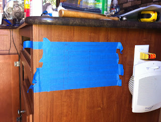
On the outside of the cabinet, facing the trailer entry door, I mounted both the remote controller display for and a big switch to turn the inverter on, since it draws a noticeable amount of power even in standby mode. I traced a pattern on masking tape and cut out square holes with a keyhole saw. The plywood is pretty thin so I glued some pieces of wood inside the cabinet into which to screw.


Here is the controller display and the inverter switch in place next to the existing AC outlet. Note that the battery is charging ... yay! The sun is not actually out this week, so only paltry +0.2A charge current.


Part 5 - Solar Wire Routing

By far the hardest wiring job was getting from the roof to the controller with no visible wires. Due to the layout of hardware on the roof, I choose to mount the panels near the front of the trailer. I also decided not to come down the refrigerator vent as is often done but to use a combiner box from AM Solar on the roof.

I ended up pulling down the lights, speakers and A/C vent covers from the ceiling in the front bedroom and poked around in the ceiling space to figure out where the roof trusses were actually located. These holes also provided a series of places where I could fish the guide-rope that I used to pull the stiff 8/2 cable provided in the SunRunner kit.

My first hop was from the hole under the light fixture ...


... to the hole under the left speaker.


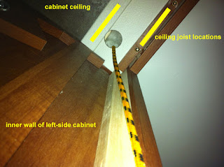
Then a short hop to a hole I drilled in the ceiling inside the left wardrobe cabinet. There are two closely spaced ceiling joists here - I drilled up between them. Because this is near the outer wall and the trusses taper down, there is just barely enough space to fish the rope.


The cable routes from this hole down along the inside wall of the cabinet out of sight. It then goes back into the stud space of the exterior wall through a 3/4" hole at the bottom of the cabinet. I temporarily removed the AC outlet which is under the cabinet to provide another place to continue fishing wire.


Finally, the wire comes back out though a matching hole in the pass-through just above the driver-side pass-through door. The wire then connects to the PV+ and PV- terminals on the controller board.


Back at the other end of the wire run, the hole shown below is in the cabinet above the sink, just aft of the light fixture where I started. The combiner box is on the roof directly above this point. No wire goes though this hole but it was needed to help fish wire from the roof.


Part 6 - Solar Panels and Combiner Box

Now the nail-biting part - drilling through the roof. Just above where I drilled the hole in the kitchen cabinet, I drilled down through the roof center-line at a point where I knew I would not hit a ceiling joist using a 3/4" hole saw. I fished the wire up from the cabinet and sealed it with a wad of butyl tape.

In this picture, you can see the wire cable (grey) coming up through the roof. The combiner box provided by AM Solar fits around this hole and screws down onto the roof, again using butyl tape in the screw holes. The wire from each panel is then wired into the terminal bars contained within the box.


The mounting brackets for the panel itself are all stainless steel. The roof of the Jayco is 3/8" plywood screwed onto trusses made from 2x2. The whole is then covered with the roofing membrane. I mounted the brackets as near as possible to where I estimated these trusses to be for added support.

The brackets are shipped from AM Solar with 3M VHB tape stuck to the bottom of the feet. This tape cannot be used with Alpha-Ply which is textured, so I had to remove it first. I found it easiest to do this by peeling up a corner and then rolling it under my thumb. Once that was removed, I put a layer of butyl tape under the bracket and screwed it onto the roof deck.

Finding an appropriate roof sealant was quite frustrating. The Jayco trailers are now manufactured with a new roofing material from Alpha Systems called Alpha-Ply. I think it might be related to TPO, but I am still not sure. Reference material on-line, including a bulletin from AM Solar, and various forum postings indicated that the commonly-used DiCor Lap Sealant causes bubbling of the Alpha-Ply material due to reaction with the petroleum distillates in the sealant. Sometimes this bubbling is only temporary, but I didn't want to take a chance.

I managed to find at RV Parts Nation a supply of Alpha System 1015 Self-Leveling Sealant which is purported to be compatible with Alpha-Ply.


I used this to seal around the combiner box and over and around the mounting feet for the panel. Note that self-leveling sealant doesn't actually level out that much.

Here is the completed panel including the optional 45 degree tilting bars. Tilted up, you can better see the sealant around the combiner box and over the mounting brackets. As per AM Solar's recommendation, the combiner box lives under the first panel for added protection from the elements.


Note that this upgraded bracket type not only allows insertion of the tilting bar, it also conforms to the slightly domed shape of the roof. Here is the panel in the lowered position which I expect it will operate in most of the time.


The second panel will be mounted just behind the first one. I will leave about 19" clear between the second panel and the A/C unit to ensure that this panel is not shadowed. If I need a third panel, it will go the same distance behind the A/C, also mounted length-wise.

Obviously, the TV antenna will have to stay down while the panels are operational since it shadows pretty much every spot on the front end of the trailer. Not a big deal for us, since we don't even have a TV in the trailer.

Update 2013.01.13 - Installed the second solar panel this weekend about 6 in behind the first with plenty of clearance to the A/C unit.