Wednesday, January 30, 2013

First View of C/2012 S1 (ISON)

This post tracks my amateur attempt at viewing comet C/2012 S1 (ISON), early in its approach, from my backyard using modest imaging equipment.  It is predicted to be an impressive sight this Fall, likely even better than C/2011 L4 (PANSTARRS) which will make its appearance in early March.

Finding the Comet

To start, I obtained orbital elements from the IAU Minor Planet Center. These elements will be periodically updated so go there for the latest values. The values I obtained were listed as

C/2012 S1 (ISON)
Epoch 2012 Sept. 30.0 TT = JDT 2456200.5
T 2013 Nov. 28.8394 TT                                  MPC
q   0.012521             (2000.0)            P               Q
z  -0.000142       Peri.  345.4975      +0.3139615      +0.5214934
 +/-0.000006       Node   295.7567      -0.7595010      -0.3634939
e   1.000002       Incl.   61.7529      -0.5697249      +0.7719565
From 1418 observations 2011 Dec. 28-2013 Jan. 12, mean residual 0".4.

Importing these into SkyTools 3 Pro, I was able to plot the projected path. It is currently in Gemini, rising shortly before dusk. By May, it will be setting at dusk. Thereafter, it will remain below the horizon during the night time hours until it rises again before dawn in September.  A 3-D diagram of the path through the solar system is shown on Wikipedia and corresponds to an orbit with inclination of about 60 degrees. This is how much its orbital plane is tipped relative to that of the Earth. You can see a more precise inclination of 61.7529 listed in the orbital elements above.  Also of interest is the eccentricity of 1.000002.  Since it is greater than 1.0, the orbit is hyperbolic, not elliptical. This means that, unless something changes the orbit, the comet will not be coming back for a second visit.

First Glimpse - Jan 30

Using SkyTools to control the mount, I centered the camera on the predicted position and took a sequence of 12 exposures, each 600 seconds long, using a 5" TMB-130SS, refractor guided on a nearby star and a QSI-540 cooled CCD camera with a luminance filter.  I was not interested in color as much as in gathering the maximum amount of light with this small telescope.

The cropped images below show the first and last observations. Sure enough, something moved! It was very gratifying to pick out something so small in the immense sky.  For context, the "bright" star in these images is HD 56222 which, at visual magnitude 6.8,  is still too dim to be visible to the naked eye under a typical dark sky. The comet, at magnitude 18 would be about 20,000 times dimmer!

Observations are between 2013.01.31 01:54 UTC and 2013.01.31 03:54 UTC from my observatory in Georgetown, Texas.  Try rolling your your mouse over the images to see a zoomed-in view.

C/2012 S1 (ISON) at 2013-01-31 01:54 UTC
C/2012 S1 (ISON) at 2013-01-31 03:54 UTC


The progression of the comet is clearly visible. Due to the exposure length, there is some smearing of the comet image; it is much too faint to try to be guided on with my equipment. Comparing against other stars in the image, the comet appears to be a bit brighter than the predicted magnitude 18.

I can't confirm any coma or tail yet as the amount of fuzziness is comparable with the evening's seeing conditions.  As an added bonus, a faint galaxy, MCG 5-18-2, is labelled at the bottom of the image.

This next, zoomed-in image is an animation of the 12 observations, representing 2 hours of elapsed time. Again, no obvious tail yet.  The "tumbling" effect you may notice is an artifact of the imaging and corresponds to a different pattern of blur in each frame.

Animation of C/2012 S1 (ISON) from 01:54 to 03:54 UTC
This screen shot from SkyTools shows the plotted trajectory over this time period


Comet Gets a Tail - Feb 7

Tonight, I went back outside and imaged the comet again. It is still in the constellation Gemini, now about 1ยบ 40' north of Tau Gem. According to a Feb 5, 2013 story by NASA, the comet is just inside the orbit of Jupiter and that, as of Jan 18, it had a tail extending over 64,400 km.  This website also gives a nice summary of the comet's history.  I had not been able to image a tail last week on Jan 30, but this evening I clearly did. This is a new development from my point of view.

I took a different approach to imaging the comet this time. Using the same equipment as before, I gathered a sequence of 20 shorter frames in order to reduce smearing of the comet image in any given frame. I confirmed that 300 seconds was short enough that the comet head was visually round - at least to within the evening's seeing conditions and my equipment.  In each frame, a consistent tail was discernible on the comet, trailing behind the path of the comet (path is left to right in the images) and angled out by about 30 degrees.

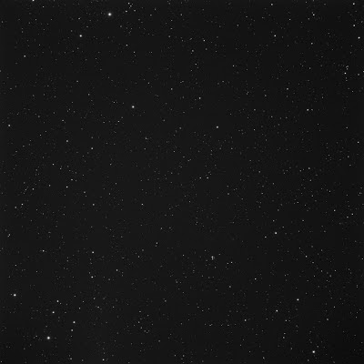
This is the single full-frame image from 03:02 to 03:07 with no processing other than a dark-frame subtraction, a gamma stretch, and conversion to JPG.  Zoom-in and try to find the comet near the center of the frame.


In order to emphasis the details of the comet tail, I combined the 20 images in post-processing. Using MaxIm DL, I first aligned the frames on the stars and stacked using "sigma clipping" mode. I then re-aligned the frames on the centroid of the comet and stacked using "averaging" mode. Finally, I normalized the background intensity of these two images and combined them using the single frame taken around 03:05 as a reference for alignment.  The combined image was then stretched and moderate noise-reduction applied to the background.  This process works because the comet only changes position, not shape over the two hours I was imaging.

In the image below, the comet is clearly visible and shows the beginnings of a tail. For reference and context, the brightest star, in the upper right corner, is TYC-02438-0115-1 located at RA: 07h09m38.3s, Dec: +31°47'24" and has visual magnitude 11.5.

I plate-solved the image spanning 03:02 to 03:07 using MaxIm DL/PinPoint. Plate-solving is a numeric technique whereby the stars in the image are identified and the patterns they make in the image are correlated against a large data-based of stars in order to find a match.  This allows the direction in which the telescope was pointing to be inferred very accurately  Once completed, the tool was then able to read off the position of the center of the comet in that frame as RA: 07h09m49.5s, Dec: +31°46'49".  For comparison, this was the position computed by SkyTools for 03:07 UTC so pretty close.  I am still impressed by how accurately the orbital elements can be estimated and used to place these fast moving objects in the sky.

Luminance image of C/2012 S1 (ISON) at 2013.02.08 03:05 UTC


The false-color image below makes it easier to see the tail, especially on a video display which has poor differentiation of dark shades.  I used the Gradient Map tool in Photoshop to accomplish this effect.

False color image of C/2012 S1 (ISON) at 2013.02.08 03:05 UTC


This screen shot from SkyTools shows the plotted trajectory over this time period


Tail is Still Visible - Feb 13

I updated the orbital elements this evening as shown below.

C/2012 S1 (ISON)
Epoch 2013 Apr. 18.0 TT = JDT 2456400.5
T 2013 Nov. 28.7665 TT                                  MPC
q   0.012472             (2000.0)            P               Q
z  -0.000387       Peri.  345.5361      +0.3145590      +0.5164431
 +/-0.000004       Node   295.6950      -0.7592155      -0.3667537
e   1.000005       Incl.   62.1109      -0.5697758      +0.7738077
From 1999 observations 2011 Dec. 28-2013 Feb. 11, mean residual 0".4.

Why do these change?  Progressively more accurate estimates of the shape of the orbit can be computed as more observations of the comet's apparent position in the sky are obtained. For example, note the slight increase in both inclination and eccentricity from before.  The last line in the text above indicates the set of observations used in the computation.  These elements are based on observations up to two days ago.

I used the same imaging and post-processing procedures as last week but used a total of 48 frames over a total of 6 hours.  The tail is more pronounced in the resulting image that it was last week.  I suspect this enlargement may have more to do with the larger amount of image data, rather than the comet itself.

This first two images show the detail near the comet at 2013.02.14 03:10 UTC.  The comet is still in Gemini and the center of the comet head is at RA: 07h03m44.2s, Dec: +31°46'03".  The brightest star here is GSC 02438-0073 with visual magnitude 11.1.   The "GSC" prefix indicates that this star is included in the Hubble Guide Star Catalog, a collection of stars that the Hubble Space Telescope uses to visually hold its camera position fixed while exposing long image. This publicly available catalog is what I use in MaxIm DL to plate-solve the images. The object near the left edge, slightly up from the comet is not a star but the galaxy LEDA 1963553.

Luminance image of C/2012 S1 (ISON) - 2013.02.14 03:10 UTC


False-color image of C/2012 S1 (ISON) - 2013.02.14 03:10 UTC


This next image shows a wider field of view.  You can zoom-in by hovering with your mouse.

False-color image of C/2012 S1 (ISON) - 2013.02.14 03:10 UTC

This screen shot from SkyTools shows the plotted trajectory over this time period


SkyTools Includes the Comet - Feb 21

Greg Crinklaw, author of SkyTools 3.0 Pro, sent me a note saying that
 "... you don't need to update the orbital elements in SkyTools by hand. Just select "Update 'current' Lists from web" on the Observing List menu of the Nightly Planner or Real Time tools. In addition to the Current Comets observing list, all of the orbital data is also updated as necessary..."  
Wow, how's that for proactive customer service! However, when I did the first observation in January, Comet C/2012 S1 was not yet included in the list of "Current Comets" he describes.  However, I tested this again last night and it is listed now.  If you are using SkyTools, this is an even easier approach to locating the comet.

More Details on Bad Astronomy - April 3

Phil Plait of "Bad Astronomy" has a posting on his blog about ISON in which he used my Feb 7 images.  Unfortunately, I had gotten the year wrong in the image legend and  have since corrected the images on this page.  It has some nice charts showing the projected path of the comet through the solar system and across the stellar background as well as other interesting factoids.  It also found a link to one of Phil's articles that lists his top 10 things you don't know about comets.


ISON Makes a Turn - April 28

Tonight's image consists of 10 frames, each 300sec using TMB-130SS.  Once again, the tail is visible. I would not read too much in the apparent size of the tail on any of these observations as the signal-to-noise ratio is pretty poor. 

The direction of the tail, however, is pretty clear and seems to have flipped direction. Specifically, the comet is now moving toward the lower left in this frame rather than toward the right.  Thus, the comet now appears to be traveling with its tail in front whereas before it was to the rear.  I assume this is optical illusion due to Earth's change in position over 3 months, similar to apparent retrograde motion in planets, and that most of the true motion of the comet is towards us.  The comet also appears to be moving slower against the star field.

False-color image of C/2012 S1 (ISON) - 2013.04.29 02:40 UTC
This screen shot from SkyTools shows the plotted trajectory over this time period. 

The motion trace taken over a broader time-frame below indicates a change in direction of the comet against the star field during early April. It had made a prior change back in November so the observations in January and February were probably during the "retrograde" segment of the apparent motion. 


The comet should now proceed back through Gemini and on through the zodiac to catch up with the Sun on November 28 in the constellation of Scorpio.

This is likely my last shot of ISON before it goes below the western horizon at the end of the month.  By around May 10 from my location, the comet will have dropped too low in the western horizon to get a clear image by the time it is sufficiently dark.  

The chart below shows the altitude of ISON (red curve) at each of the new moons from now until the perihelion late November.  I will start looking for the comet again in the pre-dawn hours in September.

Altitude of C/2012 S1 (ISON) at each new moon - assembly of screen captures taken from SkyTools 3 Pro.

Sunday, January 27, 2013

Relocation of Trailer Water Pump

After our first camping trip in the new Jayco 28BHS, we were horrified by the water pump noise.  Yes, I know they tend to be annoying, but this was much worse than any previous experience.  We could hear the pump from the outside, several camp sites away.

In this first image, you can see the initial location of the pump.  Despite the installation instructions which say "fasten to a solid surface,"  the pump was mounted to the back wall of the under-sink compartment, presumably to save space. This is an internal wall with no studs in the vicinity.  The pump itself has rubberized mounting feet but these do not do much good when mounted to an unsupported 1/8" plywood panel.  Mechanically and acoustically, this is like mounting the pump to a big drum head. I have not observed significant vibration or hammering of the piping itself but I am not sure I would have heard it over the resonating wall!

The second image shows the new location of the pump.  I detached the pump from the wall and mounted to the solid floor deck instead.  The inlet and outlet of the pump are connected to the existing PEX tubing using segments of flexible braided 1/2" hosing intended for RV fresh water applications.  The pump is turned around simply to make it easier to join to the original tubing.  Ideally, it would be better to cut back and re-route the tubing to save space ... some other time.  At least the waste basket we had under the sink still fits!

My initial test confirms that the result is much quieter.  Though I can still hear it, the level is what I expect from a water pump. At a later time, I will consider inserting an accumulator just after the pump in order to reduce the on and off pulsing of the pump that happens at low flow rate.

Update Jan 2014 - Finally decided to add a small accumulator to the pump system. This after getting frustrated with the constant pulsing of the pump which, in turn, was causing the kitchen light to flicker.  The addition of the accumulator meant considerable changes to the orientation of the pump and plumbing. This is the result


Saturday, January 26, 2013

Trailer Vent Cover

After much debating about replacing the trailer bathroom vent with a more powerful model,  we decided to defer that improvement.  Instead, we mounted a simple MaxxAir vent cover, similar to the model we had on our previous trailer.

In addition to the extra work a full vent replacement would have entailed, we were not sure whether the a strong out-draft from within the bathroom would pull smells up from the holding tanks and defeat the purpose of the vent.

Monday, January 21, 2013

Quarter Moon Jupiter Conjunction

Tonight, I saw another close conjunction of the Moon and Jupiter.  The phase was a waxing quarter moon, unlike the full moon at November's conjunction.  However, this conjunction was about half the separation at about 45 arcmin.  Seeing a clarity were rather poor this evening, so I was not able to get a clear image of Jupiter's surface bands.

Images were taken at 2013.01.21  22:15 CST from Georgetown, Texas with a Canon 450D 400mm @ 1/2000sec.


Friday, January 4, 2013

Solar Panels on Jayco Travel Trailer

During the holidays, I outfitted our new Jayco Jay Flight 28BHS travel trailer with a new battery and solar charging system. This modification will allow us to do more extensive boondocking without dragging out the generator.


The Plan

I expect we will run lights, fans, vents, furnace fan, computers, DVD player, and astronomy equipment off of the batteries. I don't plan on running the microwave and certainly not the air conditioner. I will probably not tie into the existing AC power distribution panel but simply run an extension cord from a small dedicated pure-sine inverter.

I started this project with a lot of reading. The most useful materials I found were:
After much research, I settled on a pre-configured system from AM Solar as the starting point of the project. The technical support provided by AM Solar has been excellent and the components in the kit appropriately sized. I highly recommend them as a supplier. The model I choose is the SunRunner Signature 100/25/8/6/Pro. It is based on the 2512iX charge controller from Blue Sky. I also had cause to contact technical support at Blue Sky, another company that I highly recommend. I had a long talk with the owner who took the time to explain the functioning of the controller in detail. Initially, I got a single GO-100, 100W panel. I will be adding a second panel next week and a third later, if needed.

I also planned to add a small inverter to power our astronomy computers. I chose the GPSW300 pure-sine model from Go Power! It has both a low standby current and, importantly, connections for installing a remote switch.

Finally, I planned to upgrade the existing battery from the wholly inadequate battery provided.

As an additional note, if you are considering a solar system on an RV, realize that you're unlikely to reap any cost savings from such an installation as you might expect from a home installation. Hookups are usually included in campground fees so electricity is essentially free. The real issue not energy savings, it is energy availability. If you are camping away from shore power for more than a day or so, solar provides a clean and quiet way of recharging the batteries sufficiently to make up for the electrical usage necessary for your camping enjoyment.

Part 1 - Battery Upgrade

This is the Group 24 deep cycle battery provided by the dealer ... yikes.


The first step was to rip this out and repurpose it elsewhere. In its place, I opted for a pair of Trojan T-105 6V golf cart batteries. These have a 20hr rate capacity of 225AH. I obtained them from a local golf cart vendor. The difficulty I then ran in to was that space on the trailer A-frame is pretty limited.

As described by other Jayco owners, the battery mounting track is about 1/8" too narrow to fit the new batteries. In order to rework the mounting, I first used two layers of pressure-treated plywood to build up some supports ....


... and then fitted a plywood platform on top, bolting everything through the original metal brackets. Notice that I had to notch around the support brackets for my Equal-i-zer hitch. I also had to move these brackets forward by 1.5" from the ideal 32" placement.


The batteries are housed end-to-end in a polyethylene battery box made by Century Plastics which was recommended by another Jayco owner. I obtained it on-line from All Battery Sales and Service. Others have reported having to move the propane tanks forward to make everything fit. However, by jiggling the box around on the platform, I found a placement that clears both the propane tank cover and the rounded front of the trailer ... barely.


Part 2 - Battery Cable

The next part of the project was to tie the battery to the solar charge controller. I spent countless hours pondering the best path to route cable ... mostly because I was trying to plan this project before we actually received our trailer. Pointless exercise in the end, since the configuration we actually received was not quite what I'd measured on the dealer's lot. We did receive technical drawings for our trailer from Jayco, which is a great service that they provide, but I couldn't request the drawings until we had a VIN for the trailer. Jayco does request that the drawings not be shared.

I finally chose to drill holes in the beam at the back of the A-frame and then to go up through the floor of the front pass-through compartment. I estimated around 20 ft total circuit length and computed a 1% voltage drop at 15A using 4 AWG wire.

I ordered a suitable amount of 4 AWG welding cable, 0.4" thick, from Wire and Cable to Go, another company I recommend based on their responsiveness. Due to an ordering error, I ended up with 4/0 AWG welding cable which is much thicker at 0.75". I decided to go ahead with the project using this cable. It gives 1% voltage drop over 20ft at 100A and would allow brief usage of a 1000W inverter or allow the battery bank to be upgraded in the future. By the way, I am really impressed with how flexible welding cable is, even at 4/0. My cable cutters, rated for 2/0 cable cut through this stuff like butter and make a very clean cut.

Here are the holes in the A-frame with an edge protector inserted into one of them.


The device on the left is a DC breaker that was part of the original wiring. The floppy panel at the bottom is part of the "thermal package" which we ordered with our trailer. Addition of this package made routing wire more challenging. I ended up removing the self-tapping screws that hold this giant panel in place along just the front edge and the first 12 feet of the curb-side edge. Prying down this front-right corner allowed me to access the space between the metal beams. Note that the trailer has another insulated space between the wooden joists that sit on top of these beams. I routed the cable in the lower space created by the thermal package panel. I did not have to drill through any other metal beams.

Crimping connectors onto thick cable was a new experience for me. I got the 4/0 heavy duty ring-terminal connectors shown from Home Depot. I purchased the Pico 0685t Lug Crimping Tool shown from an Amazon vendor. It works by inserting the connector under the metal plunger and banging on the top with a small sledge hammer. Works great and cost about $20. Though I used copper wiring, I decided to use Ox-Guard anti-oxidant on all joints and silicone caulk under the heat shrink tubing.


In addition to wiring the controller to the battery, I also needed to install a fuse and a shunt to measure battery current. Starting with a pair of 4x4 conduit boxes from Home Depot, I created my own access holes with miscellaneous conduit parts. I attached one box to each end of the battery box.

In the first box, shown below, I gathered all of the positive connection points (12V). One large cable goes to the positive battery terminal and the other is routed to the controller board described later. The thin 8 AWG wire is attached to the positive trailer wiring that previously connected directly to the battery. Between the two cables is an ANL fuse mounted on a home-brew mounting terminal made from stainless hardware.


The second box mirrors the first and contains all of the negative connections (0V). Instead of a fuse, the block in the middle is a "shunt," which measures a small voltage drop caused by the total current through the battery. This was part of the SunRunner kit. The small black wire ties to the trailer negative terminal wire. The small grey wire is a twisted pair which sends the shunt voltage measurement to the controller remote display.


This is the top of the box with the batteries in place. An additional 4/0 AWG section links the two 6V batteries. The whole box is a single unit and can be removed as such.


I have also added a battery watering system which I purchased from Camping World. The picture shows the black tubing snaking between the batteries and ending at a quick disconnect at the bottom of the picture.

The final thin black wire at the top of the image is the temperature sensor, included as part of the SunRunner kit, which allows the charge controller to account for battery temperature.

After all was done, I had used 23 ft of the 4/0 AWG cable in this circuit. In retrospect, the job would not actually have been easier had I used the originally planned 4 AWG cable. I am still uncertain whether the sheathing on the welding cable will survive the corrosive environment or whether I will need to rethink that part and add extra protection.

Update 2014-06-08 - Year and a half later, no problems in the battery compartment.

Part 3 - Controller Board

I mounted the Blue Sky 2512iX solar charge controller, a 30A DC circuit breaker, and the Go Power! GPSW300 inverter on a plywood board which I fastened to the back wall of the front pass-through storage area of the trailer.


Here is a detailed view of the controller board.


The standoff terminals are made from stainless steel nuts and bolts. I fully wired the board and then brought it into the trailer for final mounting and connection. I still need to build something to protect the exposed terminals from accidental shorting caused by other items stored in this pass-though.

The two cables labeled Battery+ and Battery- are the ends of the 4/0 cable routed under the trailer. Some care was needed in drilling the holes. By pressing up against the insulation-retention shroud under the trailer I was able to feel where the joists were. There was one running down the center of the trailer, one 18" to each side of center. My holes are within one of these spaces.

The smaller wire bundles labeled "Remote" are the signal wires. The right hole is the bundle from the battery box. This includes (1) the temperature sensing cable and (2) the shunt-voltage measurement cable. The temperature sensor is wired into the controller whereas the shunt-voltage cable loops back down through the left hole along with (3) the remote-switch cable for the inverter and (4) an RJ-45 cable providing serial communication between the controller and the remote display.

Update 2014-03-16 - This past week, I had the IPN-ProRemote display go dead on me. After debugging, turns out to be the serial cable back to the controller. This cable is a flat phone cable with RJ-11 jacks on the ends.  Fortunately, replacing the jacks solved the problem. In hindsight, I would recommend routing a more robust cable like an stranded copper 18/8 under the trailer for the three remote connections (serial control, shunt voltage, and inverter shutoff), terminating that to a terminal block and only running phone patch cable in an exposed area.

Part 4 - Remote and Wiring

As with any electrical project, running wires always seems to be the hard part. Turns out that dealing with the 4/0 AWG cable was the easy part! The next step was to route the cable from the controller board to the remote display. Again, lots of options, none of them easy. Voice of experience ... the space under the refrigerator cabinet houses the fresh water tank (not shown on the technical drawings we received) ... don't drill there! Fortunately, I stopped before puncturing the tank, but I do have a hole in the floor of that cabinet now to remind me of the error.

In the end, I chose to bring the three cables, enclosed in a plastic wire loom, up into the cabinet space under the kitchen sink. This view, with the drawers pulled open, shows where I drilled through the floor with a 3/4" hole saw. I used a sharp metal probe to punch down through the insulation and the protective tarp which holds the insulation in place under the trailer. This brought the bundle down into the thermal package "air space" from which I could pass it across and up into the front storage compartment.


On the outside of the cabinet, facing the trailer entry door, I mounted both the remote controller display for and a big switch to turn the inverter on, since it draws a noticeable amount of power even in standby mode. I traced a pattern on masking tape and cut out square holes with a keyhole saw. The plywood is pretty thin so I glued some pieces of wood inside the cabinet into which to screw.


Here is the controller display and the inverter switch in place next to the existing AC outlet. Note that the battery is charging ... yay! The sun is not actually out this week, so only paltry +0.2A charge current.


Part 5 - Solar Wire Routing

By far the hardest wiring job was getting from the roof to the controller with no visible wires. Due to the layout of hardware on the roof, I choose to mount the panels near the front of the trailer. I also decided not to come down the refrigerator vent as is often done but to use a combiner box from AM Solar on the roof.

I ended up pulling down the lights, speakers and A/C vent covers from the ceiling in the front bedroom and poked around in the ceiling space to figure out where the roof trusses were actually located. These holes also provided a series of places where I could fish the guide-rope that I used to pull the stiff 8/2 cable provided in the SunRunner kit.

My first hop was from the hole under the light fixture ...


... to the hole under the left speaker.


Then a short hop to a hole I drilled in the ceiling inside the left wardrobe cabinet. There are two closely spaced ceiling joists here - I drilled up between them. Because this is near the outer wall and the trusses taper down, there is just barely enough space to fish the rope.


The cable routes from this hole down along the inside wall of the cabinet out of sight. It then goes back into the stud space of the exterior wall through a 3/4" hole at the bottom of the cabinet. I temporarily removed the AC outlet which is under the cabinet to provide another place to continue fishing wire.


Finally, the wire comes back out though a matching hole in the pass-through just above the driver-side pass-through door. The wire then connects to the PV+ and PV- terminals on the controller board.


Back at the other end of the wire run, the hole shown below is in the cabinet above the sink, just aft of the light fixture where I started. The combiner box is on the roof directly above this point. No wire goes though this hole but it was needed to help fish wire from the roof.


Part 6 - Solar Panels and Combiner Box

Now the nail-biting part - drilling through the roof. Just above where I drilled the hole in the kitchen cabinet, I drilled down through the roof center-line at a point where I knew I would not hit a ceiling joist using a 3/4" hole saw. I fished the wire up from the cabinet and sealed it with a wad of butyl tape.

In this picture, you can see the wire cable (grey) coming up through the roof. The combiner box provided by AM Solar fits around this hole and screws down onto the roof, again using butyl tape in the screw holes. The wire from each panel is then wired into the terminal bars contained within the box.


The mounting brackets for the panel itself are all stainless steel. The roof of the Jayco is 3/8" plywood screwed onto trusses made from 2x2. The whole is then covered with the roofing membrane. I mounted the brackets as near as possible to where I estimated these trusses to be for added support.

The brackets are shipped from AM Solar with 3M VHB tape stuck to the bottom of the feet. This tape cannot be used with Alpha-Ply which is textured, so I had to remove it first. I found it easiest to do this by peeling up a corner and then rolling it under my thumb. Once that was removed, I put a layer of butyl tape under the bracket and screwed it onto the roof deck.

Finding an appropriate roof sealant was quite frustrating. The Jayco trailers are now manufactured with a new roofing material from Alpha Systems called Alpha-Ply. I think it might be related to TPO, but I am still not sure. Reference material on-line, including a bulletin from AM Solar, and various forum postings indicated that the commonly-used DiCor Lap Sealant causes bubbling of the Alpha-Ply material due to reaction with the petroleum distillates in the sealant. Sometimes this bubbling is only temporary, but I didn't want to take a chance.

I managed to find at RV Parts Nation a supply of Alpha System 1015 Self-Leveling Sealant which is purported to be compatible with Alpha-Ply.


I used this to seal around the combiner box and over and around the mounting feet for the panel. Note that self-leveling sealant doesn't actually level out that much.

Here is the completed panel including the optional 45 degree tilting bars. Tilted up, you can better see the sealant around the combiner box and over the mounting brackets. As per AM Solar's recommendation, the combiner box lives under the first panel for added protection from the elements.


Note that this upgraded bracket type not only allows insertion of the tilting bar, it also conforms to the slightly domed shape of the roof. Here is the panel in the lowered position which I expect it will operate in most of the time.


The second panel will be mounted just behind the first one. I will leave about 19" clear between the second panel and the A/C unit to ensure that this panel is not shadowed. If I need a third panel, it will go the same distance behind the A/C, also mounted length-wise.

Obviously, the TV antenna will have to stay down while the panels are operational since it shadows pretty much every spot on the front end of the trailer. Not a big deal for us, since we don't even have a TV in the trailer.

Update 2013.01.13 - Installed the second solar panel this weekend about 6 in behind the first with plenty of clearance to the A/C unit.