I have several goals in mind:
- allow imaging equipment to stay set up and polar aligned
- shield myself from the neighbors giant lamp-post backyard light
- reduce condensation problems on humid nights
- allow imaging on nights with wind
After considering the possibility of fabricating my own dome, I decided to purchase a pre-made Explora-Dome top and wheel kit made of durable plastic material.
This is the general design I settled on. The observator

April 2009 - After much considerat

That decision made, I spent about 2 months planning out a design on the computer refining it until everything fit together in theory. I then printed it all up and got my building permit approved by the City of Georgetown

The observator

The area behind the shed is cleared and footing locations are flagged. There are three lines of footings for the main beams and two locations for pier holes. One pier will be in the observator

Here is the planned layout of the footings. Note that these drawings reflect the modification I made to address vibration problems encountered during the build.

This is the elevation plan for the footings and one of the piers. During the design, my biggest uncertaint

June 2009 - I get started on digging footing holes. I discover that the ground is all rock and clay. My attempts to dig with a shovel or post-hole digger are fruitless. So are any thoughts of using a power auger. I recall that when our fence was built the contractor broke an auger bit. I finally resort to a new tool ... a "breaker bar". Its a steel bar with one end pointed and the other end beveled. Basically, it breaks the rock along the edge of the hole. By this point, we are into the heat of what will be one of the hottest summers on record. Who needs to go to the gym to lose weight when there are holes to be dug!

Getting the rock and clay out turned out to be easier with a hand trowel than with a shovel. Then the post-hole digger was not the best implement.

All footing holes are dug and the forms are ready to drop in. I have one pier hole dug the other yet to go. It took me about 45 minutes to dig one footing hole and about 8 hours for the pier hole.

When I finally gave up on digging the pier holes, I had a 3 foot diameter hole, 3 feet deep. Fortunatel

Look ma, fill'er up with water and we'll have us a nice jaccuzzi.

Forms placed into footing holes and lined with gravel. These smaller 8" forms were easy to find at Home Depot.

I had planned on using batten boards to line up the footings. That plan went out the window the moment I tried to hammer in a wooden stake into the ground. I ended up sinking metal rods and stretching twine between them. This does not make it easy to adjust alignments

Here is a detailed view of the wooden pier fasteners and the alignment process.

My order from Explora-Dom

The dome is 8 foot in diameter and looks smaller in person than I imagined. Vali, of the Muddy Paws, wonders how to get in the new "dog house". Keeping the dome "round" proved a losing battle while storing it.

July 2009 - Now its time to build the pier and beam foundation for the deck and building. The dark colored beams are 2x10 and the lighter colored ones are 2x8. The 2x8 sections support decking and the 2x10 the observator

Here is a side view of the same drawing. The middle beam joins one board of each height.

Building the beams using a combinatio

Here is a detail of the corners. I used galvanized hardware for all of the joinery ..

Beams and joists go up next. Getting the beams on top of the posts solo was a challenge. Note that I am building the foundation before I pour the piers. This allows me to use the joists to brace and plumb the pier forms. I have left off the end joists to get the cement mixer close enough to directly pour the big base footing.

I found this picture very artistic! The boxed in area between the joists is nicely centered over the hole. The last two joists to the left of the doubled joist are only loose in their hangers. I pulled these out in order to pour directly into the hole for the first layer.

Rebar structure is assembled and braced in place while I plumb. The rebar extends down about 6" into the gravel to hold it in place.

Another artistic picture ... I found the pre-made rebar rings at a concrete contractor supply shop along with the large forms used for the lower base. I also found 10 foot long 12" forms for the main pier, saving me have to attempt to join two of the 4foot forms sold at Home Depot and hope they held under the pressure of the pour. Based on my later experience, this would never have worked.

This view shows the trick of using the joists and extra boards to exactly plumb the form and hold it solidly in place. I needed no other bracing for the rest of the job as this was rock solid.

After pouring the bottom footing about 1.5 feet deep and letting it firm up for an hour, I placed the pier form down around the remaining rebar structure to continue the pour.

Did I mention there is no way to get a concrete truck back here. It was a long weekend but thank goodness for the two-sack mixer rental which sure beats the hand mixing I did for the footings.

Having the mixer up on the deck gave me enough elevation to shovel directly into the form. This was the other reason for building the foundation before pouring the piers, having a platform to shovel from without lifting over my head. With help from my wife, we shoveled and tamped down the concrete two bags at a time.

Finished column down into the ground and back-filled with soil. All looks clean, no big bubbles or voids.

After the forms come off I attach one of "Dan's Pier Plates" onto the J-bolts which I sunk into the concrete after it was poured. I highly recommend these plates. We also have one for the other pier with an Atlas EQG adapter. I made a duplicate plate out of wood and attached the bolts to it before sinking them into the concrete. That way, I was sure that the bolts would align correctly and be vertical after everything set. I used a compass to align the north bolt and had no problem getting within a few degrees of correct polar alignment.

For my CGE, I use the big orange knobs from ADM to assemble easily in the field. These do not fit on the standard CGE adapter plate. Dan from "Dan's Piers" made me a custom, trimmed down, version of the plate which allowed clearance for the bottom set of knobs. Way to go Dan for awesome customer service!

This shot shows both piers. The right one will be enclosed in the observator

August 2009 - At this point, I did some vibration tests on the pier by kicking it and feeling at the plate. To my horror, I felt a noticeable vibration at about 10Hz. Though when I attached the mount and scope, the vibration amplitude was greatly diminished, I was still not pleased. My 12" pier section is pretty high, almost 7 feet; that might be the problem.
Time to retrofit the pier. First I dug out all the back-fill. This is where having the foundation in place was a real pain in the neck ... and back. I also needed to get a 24" form down into the hole but there is no space to lower it down. I ended up slitting the 24" form up one side, prying it open, and wedging in down under there. I then had to build bracing to keep the concrete from busting the seam apart. Even with bracing boards and cam-tighte

Vibrations problems solved, time to move to the next step. After shoveling in about 3 yards of gravel on top of "weed barrier", I built the sub-floor from 3/4" OSB. Hard to see in this picture, but the sub-floor is several inches above the surface of the rest of the deck. Several months later, I found grass growing through the barrier!! I guess it was not sold as "grass barrier".

Here is plan for the wall. The right side of the observator

There is a full wall on this side

whereas this wall has the door opening. The storage bay area will be constructe

The walls go up pretty quickly. I have a 10 foot square section around the pier as is typical for Explora-Dom

I am opting for a non-standa

This part of the roofing is a simple lean-to over the storage bays. It starts just under the level of the main roof trusses and slopes down at the same 10 degrees.

The main part of the roofing is where I decided to be creative. Rather than opting for a square roof and using the available plastic roof sections, I decided to opt for an octagonal roof design with shingles that match the house and shed. Time will tell whether I have heat retention problems with shingles. In the meantime, this proves to be a fun trigonometry exercise.
Building the roof truss is actually very easy. There is a bit of clever cutting of the boards with the circular saw set to the right cut angle but assembly is actually a series of 3 layers of nested sections, each of which joins the previous layer at a 45 degree angle allowing the use of standard galvanized hardware. This ends up being very solid and I was able to assemble myself .
Building the roof truss is actually very easy. There is a bit of clever cutting of the boards with the circular saw set to the right cut angle but assembly is actually a series of 3 layers of nested sections, each of which joins the previous layer at a 45 degree angle allowing the use of standard galvanized hardware. This ends up being very solid and I was able to assemble myself .

The sheathing on the roof consists of custom-cut 3/4" panels. The elevation attempts to show show how I joined an octagon to a circle. This was my biggest headache of the project.

September 2009 - Cutting the goofy shaped roof sheathing sections, for some reason, was harder than I expected. I wasted several of these trying to get the shape right. There are 4 big panels in the corners and 4 smaller panels on the sides. All 8 section slop radially away from the center at 10 degrees. We hauled the dome up onto the deck to keep it more level. I think it warped a bit in the intervenin

Roof in place, I came back and added a fake window hole in which to mount an AC unit. This view also shows that the lean-to section follows the same slope as the octagonal roof pitch but offset down by a few inches.

All the roofing panels are in place and the rotation ring placed to fit. Also dry fit some flashing sections.

To join the sloped octagonal sections to round flat ring, I used a set of 2x6 boards cut to fit over and and behind the back edges of the roof panels. Ring is attached to these boards, once they are painted, with 8 L-brackets (not shown) and silicon applied to seal underneath ring. This is the point where I do final shimming and stretching of the ring with straps to get it as round as possible.

View from underneath shows the truss structure. The overhang of the rotation base ring, and the resulting hole, is corrected later by adding another octagonal inner "ring" of 2x4.

Attaching wheels. This view shows the scale of the building. Basically a little Hobbit house.

Details of the wheel kit provided by ExploraDom

All wheels in place. Ring assembly painted and sealed.

The dome is up! My wife and I started to heave this up together by leveraging it up the lean-to side. Not sure we would have had the strength to do it. A neighbor came over and the three of us man-handle

A layer of 15# building felt goes up all around. See the loose OSB scraps? I can state from personal experience that these need to be nailed down ... I will leave it to your imagination.

View of ring from inside. At the top is the dome surface. I ordered the black-line

T1-11 paneling goes up. I wish I had left more overhang on the roof panels in retrospect but that will get fixed with some trim pieces.

Paneling hangs down to where a decking board can still slip underneath and still extends about an inch below the sub-floor. This was the point of the dual height deck construction. NOTE: this degree of flashing proved to be insufficient. Later retrofit put real vinyl flashing extending down past the top of the joists.

I extended the overhang of the roof out with some 1x2 trim pieces painted all around and covered with the drip edge. The shingles are installed on the lean-to part of the roof but "gabled end" above it has yet to be done.

To edge these octagon bend points, I install a section of drip edge along the slope with 6" bit continuing along the horizontal part. The bend was done by notching out the bottom edge. I then added another full length horizontal piece over this.

The hobbit door. This is a cut-down 32" solid-core interior door which has been well painted. The bottom of the door went through various treatments

Threshold treatment worked well. I installed a L-shaped flashing piece down first to protect the exposed sub-floori

This is a dry fit of the custom over-lappi

Back to the flashing on the lean-to. Originally I thought to leave the edge exposed so I painted it.
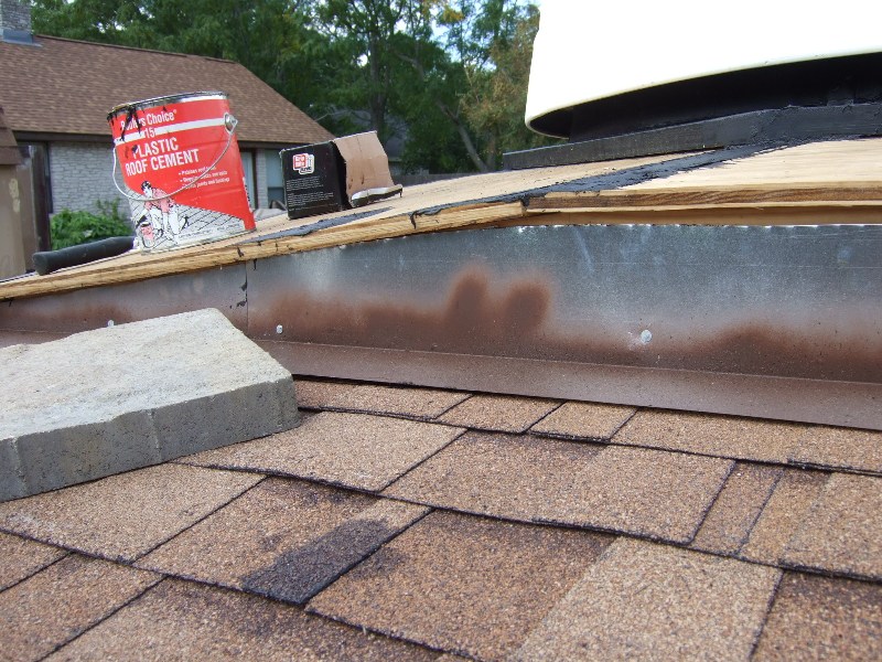
A section of T1-11 paneling goes in place over the flashing. I affixed another decorative row of shingle with roofing cement. Also have done one section of shingling on the main roof.

Electrical was the one part I hired some help for. Mostly, I did not want to have to deal with the city planning directly on this one. I did convince the contractor and the city to let me do all interior work and let the contractor trench, conduit and hook into the main panel. We ran a 20A (10ga) circuit out to the observator

Finished trench leading to the observator

Conduit ends back on the corner of the house. Rest of the cabling runs up the inside the wall and through the attic. No other conduit shows on the house exterior. I was very pleased with this.

I am left free to do my own interior wiring to get things where I need them including eventually the wiring on the pier.

The "bringers of muddy paws" provide their value-adde

October 2009 - Shingling is finally done and decking goes up. Skirting board is balanced in the rocks to check the fit. Still need to find a better landscapin

Viewed from the other direction, this shows the second pier where my wife's scope goes. She did not want to be in a claustroph

AC unit is now installed in the building.

AC sits on a custom-mad

Some super-size

On the inside, the brown 1x4 trim pieces are wedged in to brace the AC in place. The upper pieces play the role of the window sash which is meant to brace this type of AC in place.

Final treatment of the rim. This is a three-laye

Inside, the storage bay area is divided between storing cases ...

... and a place for napping during exposures.

My wife's Orion 100ED / Altas-EQG assembly goes up for a test drive.

On the inside, the TMB-130SS / CGE gets its first light test-drive

November 2009 - Deck skirting added all around. This is a 2x10 (16ft) of PT pine like the deck framing. It may be painted the same brown as the trim, I am not sure what I like better.

Today I learn how to drive a skid front loader to remove dirt in the planting beds around the deck and replace with better planting soil. This is much better than a Tonka truck. Soon after soil transplant completed, we got a long heavy downpour ... I now have a quicksand moat around the project.

Finally solved the water runoff problem by burying a row of limestone bricks into the ground to create a form to keep gavel in and muddy run-off out. Ran another row around the outside to create a planting bed.

Planting bed on back side

Google Earth catches up with our project. Dome is visible up and to the right of center.

Start constructi

More detail on the pier box

Computer station in one corner. Internet to observator

Eye-level view down on the table top on the pier framing and the "counterto

Finished pier box

Birds-eye view down into the observator

Another view from the slit showing the pier table in more detail.

April 2010 - I finally get around to requesting the final inspection for the building permit. I guess the observator

Fantastic, inspiring job. My 84 year old father has asked me to move his observatory from Salt Lake City to rural and dark Torrey, Utah. https://thotsandshots.net/2016/08/24/moving-dads-observatory/ I will use a cement pad, but Dad encourages me to build a larger base, such as yours. With your permission, we may borrow some of your ideas.
ReplyDeleteDid you run ethernet to the observatory from the house? I don't see that you did but I am wondering about separation from power requirements. Again, great job!
I use a pair of "ethernet over power" transmitters attached to that dedicated circuit. Electrician added another receptacle in the house to plug in one of the transmitters near my router
DeleteInteresting, I will look into that ethernet approach. Thank you!
DeleteI read through your page. Since you are already looking at some sort of new underground conduit for the power, why not run another parallel conduit for communication wires. I would not use the same conduit, even if it were allowed by code.
DeleteYes, we will run a shielded, waterproof ethernet cable in a separate conduit. The question would be a separate trench given that the ground is mostly sandstone and trenching is problematic.
ReplyDeleteHi Edward- Is your dome ring 8' in diameter? Thanks much, Mark
ReplyDeleteYes, I have an 8' model with black painted interior. That was the only size available at the time. Diameter works fine for me with my telescope. If I were going to change anything, it would be to make the base walls taller and use a higher step-stool.
DeleteThe dome I am moving of my father's is an 8' too (by Observa-dome). Dad's round wall is 67" high on an 8' diameter base. He has only mentioned that he wishes he had more room inside. Thus I searched for and found your plans. So good of you to be there! He uses his setup exclusively for photography as far as I know. I am going up to the observatory with him tomorrow and will ask him about his visual observing experience.
DeleteBTW- I am planning on using two separate conduits and will space them as far apart as practical in the same ditch. -Mark
ReplyDeleteAfter 10+ years of usage, here are a few changes I would make:
ReplyDelete- Newer ExploraDomes have metal rolling track. The plastic one has always been poorly trued. The skakeboard wheels have also disintegrated and I had to source some non-identical replacments.
- I would use the new sealant tapes to protect the tops of all of the deck joists, espcially around the observatory. I had to do a replacement of some of the joists due to water damage.
- Better flashing is needed on the lower section, extending down and protecting the joists
- Though the roof did not leak after I built it, it did after the roofers replaced shingles after big hail storm. I would re-think the upper flashing to be more recognizable to a roofer. The octoganal shape complicates this.
- The pier design has held up and performed very well.
- Cool down of the building is not easy. Perhaps install more windows that can be opened to circulate air out prior to imaging.
- I would follow my own advice and run a parallel communications conduit. The Ethernet-over-Power adaptors work but are more flaky than I had hoped.