Imaging Train
The imaging train for these tests is the following:
- TMB-130ss refractor, focal length 910mm at f/7
- Feather Touch focuser option [Starlight Instruments, FT-3035]
- Replacement focuser end cap with AP 2.7" threads [Starlight Instruments, EC35-505AP]
- 0.75x Focal Reducer [Astro-Physics, 27TVPH]
- Adapter from 2.7" threads to SCT threads, 8mm insertion length [Astro-Physics, ADA204]
- Adapter from SCT threads to T threads, 18mm insertion length [Antares]
- T-thread extension barrels, various lengths
- Baader T2 Quick-changer, 15mm insertion length [Alpine Astro, T2-6,7]
- QSI-540ws with T-thread mounting plate, 21.4mm diagonal
The camera I am using is the QSI-540ws which has a KAI-04022 sensor with 7.4um pixels. The sensor is square with a 21.4mm diagonal. Although all tests are based on that camera, the popular KAF-8300 sensor included in many of the new affordable CCD cameras has nearly the same diagonal size, 22.5mm, though not square. I would expect nearly the same geometry and curvature results.
Geometry Results
For each T2 extension tube length, I measured the distance from the back edge of the AP-27TVPH focal reducer to the "seam" of the QSI-540ws camera body. This seam between the blue and black parts is approximately 1mm in front of the CCD sensor according to QSI Imaging technical drawings. This distance is reported in the table below as CCD (mm).
For each extension length, after bringing the image into focus with a Bhatinov mask, I noted the position on the measurement scale of the FT-3035 focuser. This is reported in the table as Focus (mm). You can see that the set of tests span most of the focusing range of the FT-3035.
To get an accurate measure of the reduction factor, I used the PinPoint plate solving feature in MaximDL to compute the image scale of each star field I imaged, reported as Scale ("/px), and the corresponding focal length. The magnification factor, reported in the table as Mag (x), is the ratio of the focal length computed with the focal reducer to that computed without the focal reducer.
| CCD (mm) | Focus (mm) | Mag (x) | F-Ratio | Scale ("/px) |
|---|---|---|---|---|
-
|
-
|
1.000
|
f/7.0
|
1.68
|
132
|
22
|
0.743
|
f/5.2
|
2.26
|
124
|
37
|
0.754
|
f/5.3
|
2.22
|
117
|
51
|
0.765
|
f/5.4
|
2.19
|
102
|
75
|
0.786
|
f/5.5
|
2.13
|
81
|
109
|
0.815
|
f/5.7
|
2.06
|
Field Curvature Results
For each setting, I shot a 20 sec, unbinned image of the star field around the bright star Sadr in Cyngnus to test geometry and illumination. The image below shows the full frame for each of the focal reducer positions. All images were subjected to identical gamma stretching so relative brightness can be compared.
 |
| Sadr star-field at each focal-reducer spacing |
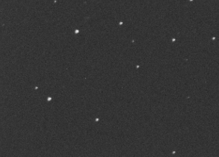
For each of the star field images, I then magnified the lower-left corner of the frame to see the degree of radial "smear" in the image. Similar visual results for the other three corners are not shown. These tests also show the effect of some under-sampling resulting from the use of the focal reducer. My skies are usually around 2" to 3".
 |
| Bottom-left corner with no focal reducer |
 |
| Bottom-left corner with 81mm focal reducer spacing |
 |
| Bottom-left corner with 102mm focal reducer spacing |
 |
| Bottom-left corner with 117mm focal reducer spacing |
 |
| Bottom-left corner with 124mm focal reducer spacing |
 |
| Bottom-left corner with 132mm focal reducer spacing |
As expected, the curvature effects are more noticeable at the larger reduction factors. The image for 81mm has more distortion than I expected. Looking over the full frame, the 132mm configuration was noticeably worse. I am going to try to stick with something around 120mm though the reduction is 0.76x at that distance. The field is not as flat as I had hoped but will probably be a reasonable compromise in order to shorten the required imaging times.
Vignetting Results
For each setting, I shot a 0.1 sec flat field using an Aurora electro-luminescent panel. For the focal reducer tests, this placed the peak intensity near the 40% grey point and about half that for the non focal reducer test.
In MaximDL, I used the Line tool to graph the illumination intensity across the diagonal of the sensor. I also set the white and black point of the images to the span the range of pixels. Each of the images below shows the stretched image and the line graph. I do not have any more sophisticated curvature analysis software but this gives the general idea.
Eyeballing the lowest and highest averaged values along the curve and taking the ratio, the vignetting gives a 5% decrease in the corners without the focal reducer and up to 8% with the focal reducer. Both of these are easily corrected with a flat-field normalization, so not much of a concern with this sensor size.
 |
| Flat-field illumination with no focal reducer |
 |
| Flat-field illumination with 81mm focal reducer spacing |
 |
| Flat-field illumination with 102mm focal reducer spacing |
 |
| Flat-field illumination with 117mm focal reducer spacing |
 |
| Flat-field illumination with 124mm focal reducer spacing |
 |
| Flat-field illumination with 132mm focal reducer spacing |
Flip Mirror Options
When imaging, I like having the ability to quickly switch to an eyepiece to get a wider field of view to provide context, to try looking at a target visually, or simply to align the mount without removing the camera. I had been using an imaging train that I put together for this purpose. However, with 120 mm to work with now, that system is no longer usable. The Vixen flip-mirror insertion length is too large.
After much hunting, I found a candidate solution using the TFlip mirror from Teleskop Service which has an 82 mm insertion length. In the USA, I was please to find it offered by Optcorp. I also found an on-line review by a Polish amateur astronomer.

Update 2012.09.02 - Last night, we had clear but slightly hazy skies under a full moon. I tested the focal reducer on the Pelican Nebula under H-alpha light. The first processed image below is from a stack of 23 Ha images, each 15 min. I chose the 117mm extension length giving 0.7657x according to MaximDL plate solve or a focal ratio of f/5.4


Way more stars then I saw that night with the naked eye. We could see a bit of the Milky Way, though.
ReplyDeleteVery good writeup, useful info. I'll be testing it with a 250mm RC.
ReplyDelete